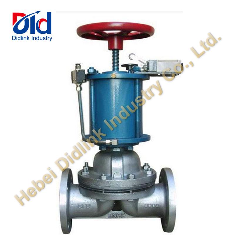
Principle of pneumatic control valve, working principle of pneumatic control valve

1. Working principle of pneumatic control valve
The pneumatic control valve uses compressed air as the power source and the cylinder as the actuator. Through the electric valve positioner, converter, solenoid valve, cut-off valve and other accessories, the pneumatic control valve achieves switching or proportional adjustment, and receives industrial control signals. The automatic control system is used to complete various process parameters, such as flow, pressure, temperature, etc., to adjust the pipeline medium. The characteristics of pneumatic control valve are simple control, fast response, intrinsic safety, no need to take additional explosion-proof measures. Pneumatic control valve is usually composed of pneumatic actuator and control valve. Pneumatic actuator can be divided into single acting and double acting. The single acting actuator has a return spring, while the double acting actuator has no return spring. When the origin or sudden fault occurs, the single acting actuator can automatically return to the initial opening or closing set by the valve
Closed state. The pneumatic control valve is divided into two types according to the action mode: the so-called normally open type and the normally closed type. The opening or closing of pneumatic control valve is usually through the negative action of actuator and valve state structure. Different assembly methods are implemented.
2. Action mode of pneumatic control valve
Air to open (normally closed) is to increase the opening of the valve when the air pressure on the diaphragm head increases. Directional action, when the upper limit of input air pressure is reached, the valve is fully opened. On the contrary, when the air pressure decreases, the valve moves in the closing direction, while when there is no air input, the valve is completely closed. Usually, we call the gas opening control valve as the failure shut-off valve. The action direction of air closing (normally open) is opposite to that of air opening. When the air pressure increases, the valve acts in the closing direction: when the air pressure decreases or does not decrease, the valve is in the open direction or fully open. Usually, we call the gas shut-off control valve as a fail open valve. The selection of gas is based on the safety of process production. When the air supply is cut off, the control valve is safe in the closed or open position.
For example, in the combustion control of the furnace, the regulating valve is installed on the fuel gas pipeline to control the supply of fuel according to the temperature of the furnace or the temperature of the heating material at the outlet of the furnace. At this time, it is safer to use the gas valve, because - once the gas source stops, the valve is closed more than the valve is fully opened. If the air supply is interrupted and the fuel valve is fully open, there is a risk of overheating. Another example is a heat exchanger cooled by cooling water. The hot material is cooled by heat exchange with the cooling water in the heat exchanger, and the regulating valve is installed in the cooling water. In the pipeline, the material temperature after heat exchange is used to control the amount of cooling water. When the air source is interrupted, the regulating valve should be in the open position. It is safer to use air closed (FO) control valve.
3. Pneumatic control valve positioner
The positioner of pneumatic control valve is the main accessory of control valve. It is used with pneumatic control valve. It receives the output signal from the regulator, and then controls the pneumatic control valve with the output signal. When the control valve is actuated, the displacement of the valve stem passes through. The mechanical device feeds back to the valve positioner, and the valve position status is transmitted to the upper system through electrical signals. According to the structure and working principle of valve positioner, valve positioner can be divided into pneumatic valve positioner, electrical valve positioner and intelligent valve positioner. The valve positioner can increase the output power of the control valve, reduce the transmission lag of the regulating signal, speed up the movement speed of the valve stem, improve the linearity of the valve [valve], overcome the friction force of the valve stem and eliminate the friction force of the valve rod. The unbalance force is affected to ensure the adjustment. Position the valve correctly.
The actuator is divided into pneumatic actuator and electric actuator, which are divided into straight stroke and corner stroke. It is used to automatically open and close various cutting and wind boards.

 JACKY
JACKY